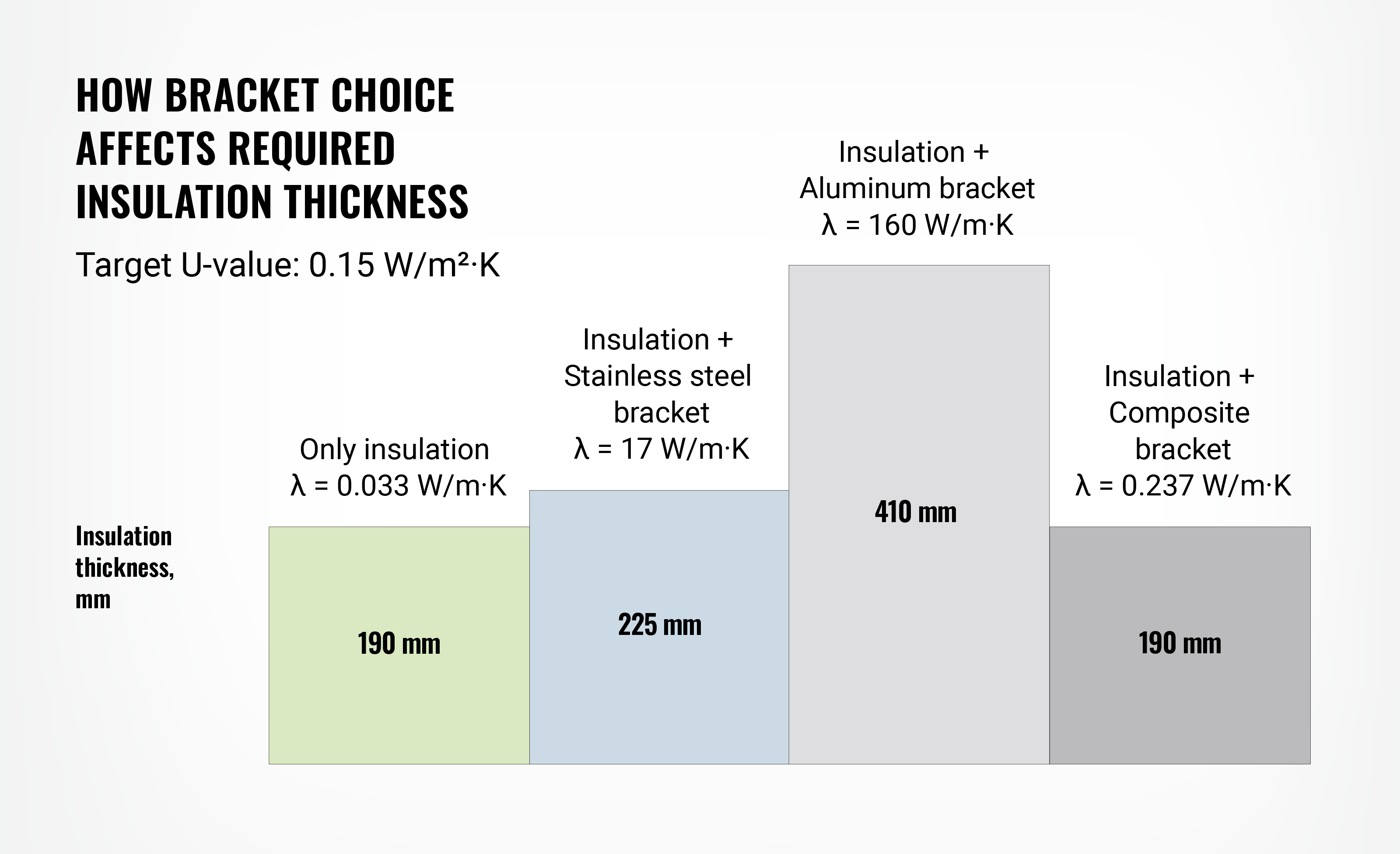


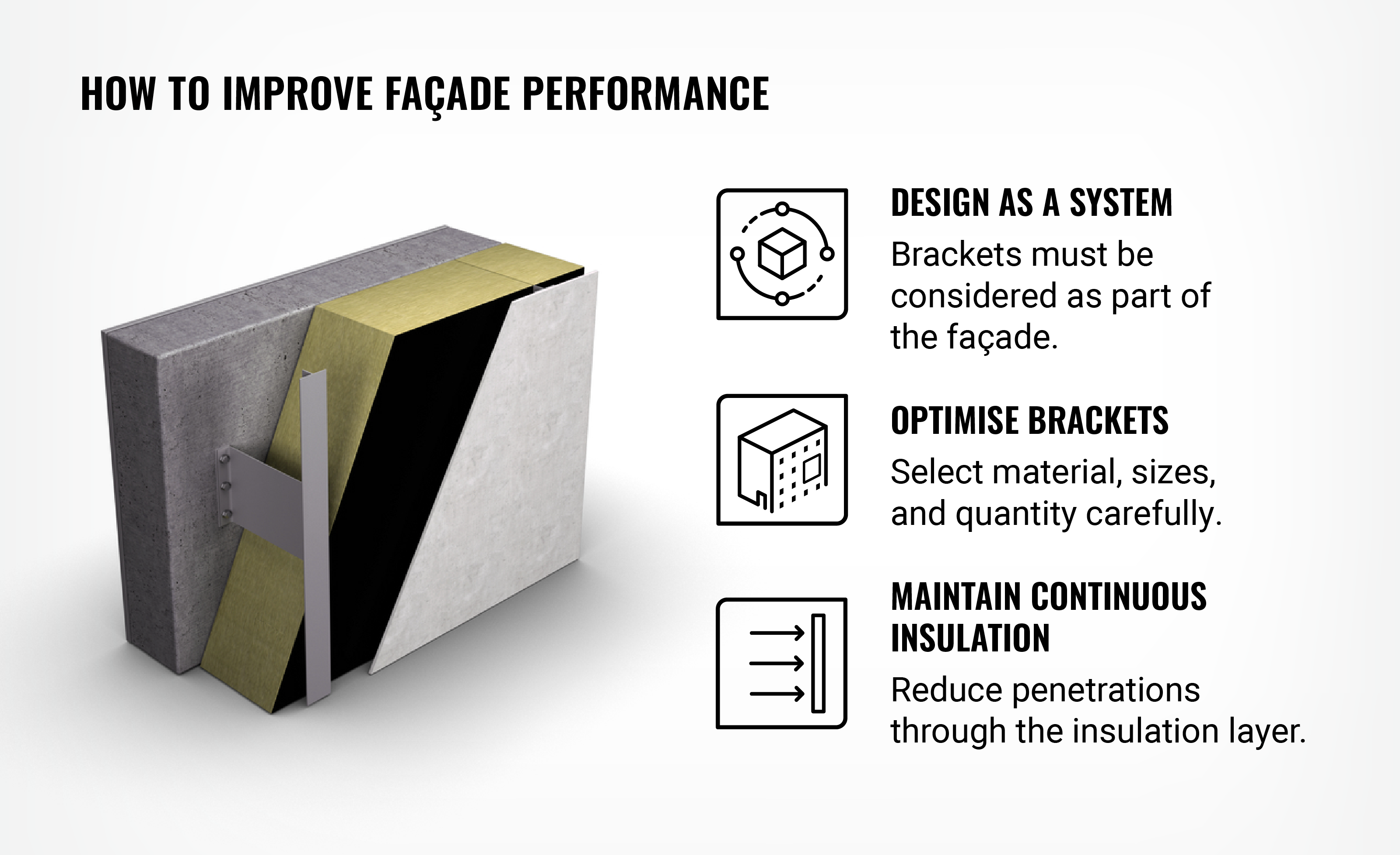
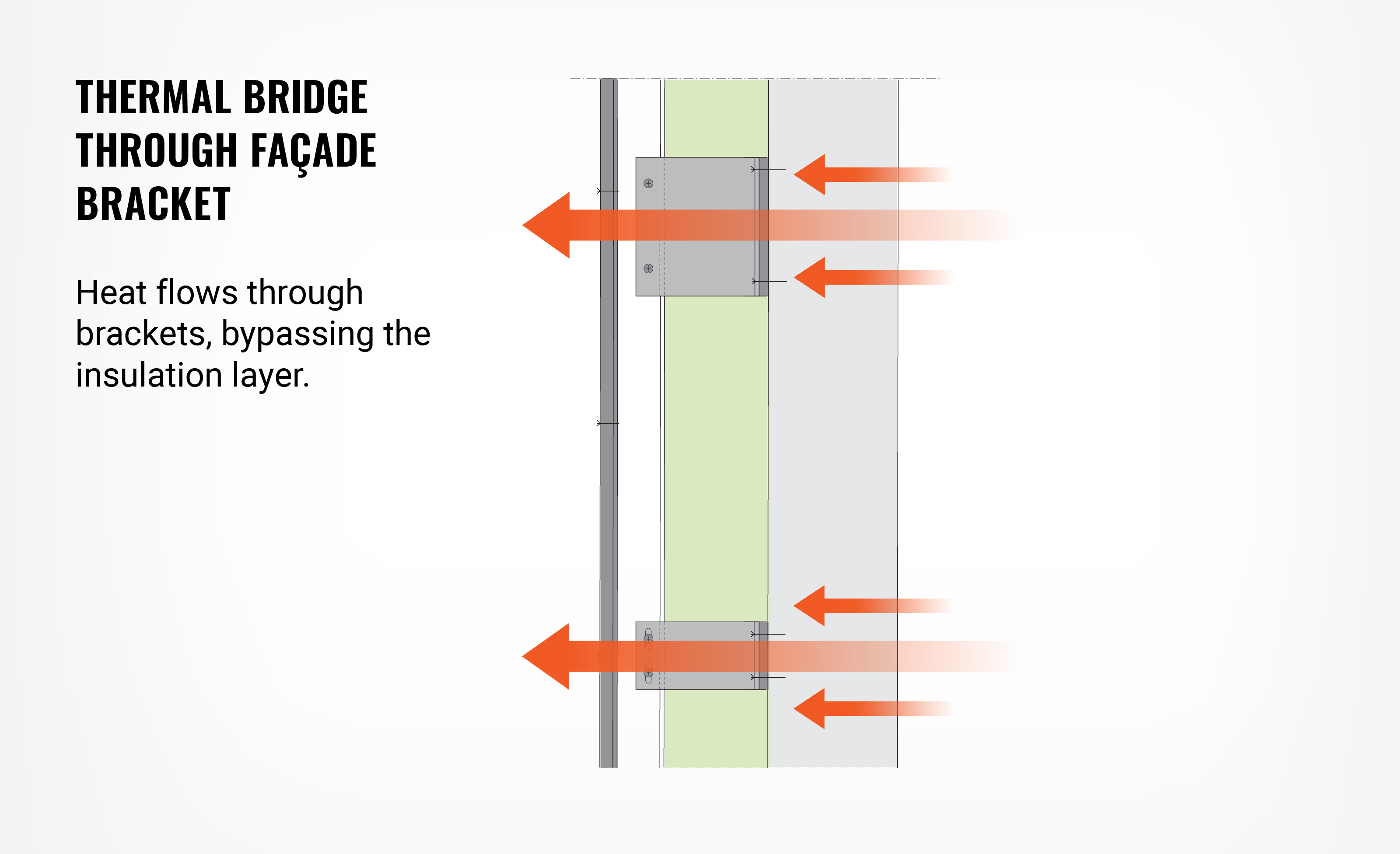
“If you want to assess the energy efficiency of a ventilated facade, you will have to pay special attention to wall brackets and fasteners that penetrate the insulation layer. Metallic elements in particular conduct heat extremely well and can significantly reduce energy performance,” notes Alex Lalla, Application Manager, Building Insulation at OC Paroc.
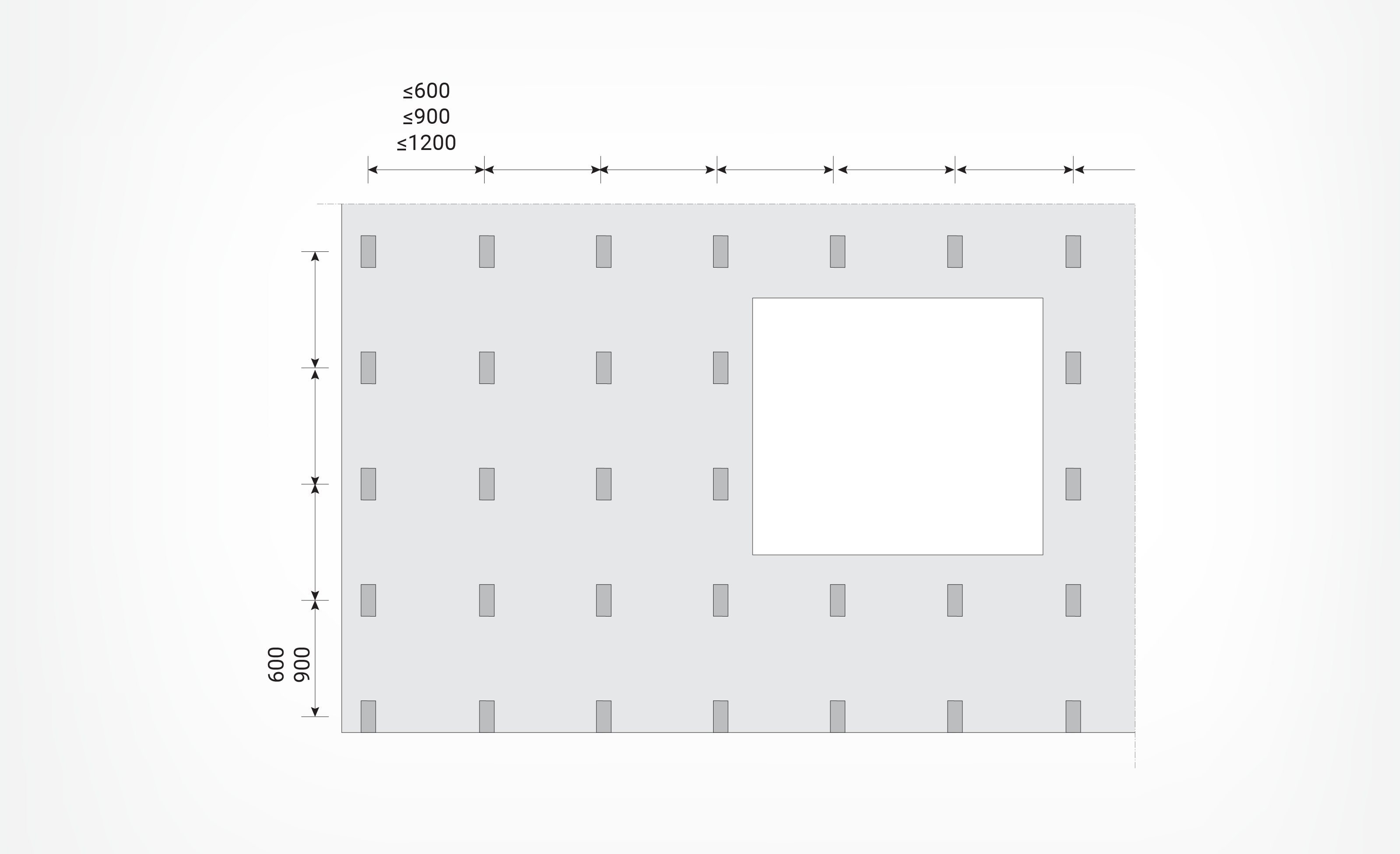
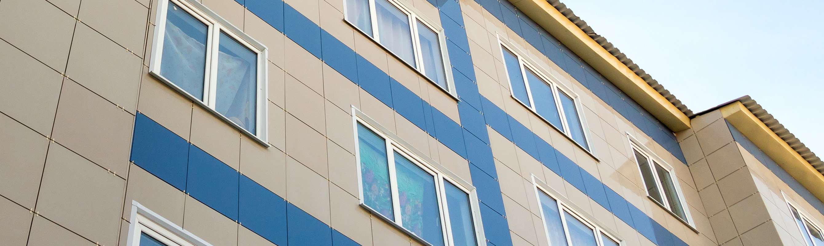
A facade’s thermal performance is the result of the combination of the insulation, substructure, and quality of execution. Wall brackets are the instrumental part of this combination: they are structurally necessary, yet they largely determine how much the insulation layer is weakened by thermal bridging.